model name TR 40-16bit-3U-opt.
The units have 32k memory, which can be configured by the user for shorter memory depths. The oversampling can also be configured by the user so that 20MHz, 10MHz, 5MHz, 2.5MHz and 1.25MHz sampling rates can be achieved while keeping the number of bins constant. Per default the units ship with a 16k trace length and sampling speed of 40MHz.
In order to change the transient recorder default memory length you need to unmount the transient recorder first (see the for mounting instructions).
Then open the side panel.
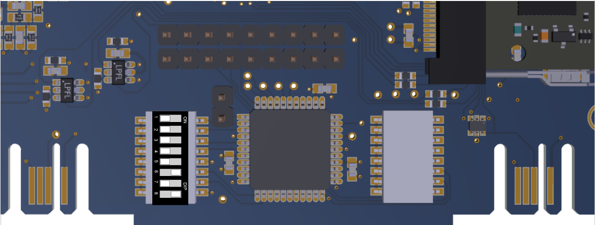
For TR 40-16bit-3U-opt the address switch is in the lower middle of the board.

The black dip switch for the address selection also hosts the memory length selection, the following lengths can be selected.
| memory depth | 6 | 7 | 8 | Sample | 16k Address 0 |
|---|---|---|---|---|---|
| 512 | OFF | OFF | OFF |  | |
| 1k | ON | OFF | OFF | ||
| 2k | OFF | ON | OFF | ||
| 4k | ON | ON | OFF | ||
| 8k | OFF | OFF | ON | ||
| 16k | ON | OFF | ON | ||
| 32k | OFF | ON | ON |
Transient recorder memory/range resol./repetition rate
| sample rate | 10 | 20 | 40 | 80 | MHz | |
|---|---|---|---|---|---|---|
| memory | range resol. | 15 | 7.5 | 3.75 | 1.875 | m |
| 256 | max. rep. rate | 31.25 | 52 | 78 | 103 | kHz |
| max signal | 3.84 | 1.92 | 0.96 | 0.48 | km | |
| 512 | max. rep. rate | 15.6 | 26 | 39 | 51 | kHz |
| max signal | 7.68 | 3.84 | 1.92 | 0.96 | km | |
| 1K | max. rep. rate | 7.81 | 13 | 19.5 | 25.9 | kHz |
| max signal | 15.36 | 7.68 | 3.84 | 1.92 | km | |
| 2 K | max. rep. rate | 3.90 | 6.5 | 9.75 | 13 | kHz |
| max signal | 30.72 | 15.36 | 7.68 | 3.84 | km | |
| 4 K | max. rep. rate | 1.95 | 3.25 | 4.88 | 6.5 | kHz |
| max signal | 61.44 | 30.72 | 15.36 | 7.68 | km | |
| 8 K | max. rep. rate | 0.97 | 1.62 | 2.44 | 3.2 | kHz |
| max signal | 122.88 | 61.44 | 30.72 | 15.36 | km | |
| 16 K | max. rep. rate | 0.48 | 0.81 | 1.22 | 1.6 | kHz |
| max signal | 245.76 | 122.88 | 61.44 | 30.72 | km | |
| 32 K | max. rep. rate | 0.24 | 0.40 | 0.61 | 0.81 | kHz |
| max signal | 491.52 | 245.76 | 122.88 | 61.44 | km |
with 10 kHz Laser the following trace lengths will work
| sample rate | 10 MHz | 20 MHz | 40 MHz | 80 Mhz |
|---|---|---|---|---|
| bins | 750 | 1300 | 1950 | 2660 |
| tracelength (km) | 11.25 | 9.75 | 7.3 | 4.9 |
To work with these tracelengths set the DIP Switch 5, which turns the configurable tracelengths on, to ON.
options:
- AP
- separated inputs for analog and photon counting. Makes sense for APD users who also detect weak PMT signals (Raman signals, etc). One trigger source - two detectors (APD + PMT in photon counting). See also situations when this is not a good option
AP Considerations
There are situations where the AP option looks like a economic good idea at first glance but the side effects are unwanted- Depolarization: Use analog for the strong parallel and photon counting for the weak depol. channel. This works as long as you do not hit an strongly depolarizing ice cloud...
- N2 in water raman system: You typically send so much light out at 355 to see a water raman signal that the N2 which has 3 orders of magnitude more cross section would require a neutral density filter, where the expensive photons that your system emits, have to die to make the photon counting possible
- Daytime water raman (408nm): 408nm is not in the solar blind region
any more, so typically your background signal goes up when the
sun rises. If this signal background exceeds 60 MHz (roughly 1 mV with our PMT)
the dead time correction for this is already significant. But more
sadly most of your linear dynamic range of the photon counting has
gone. Dead time correction after 90 MHz of observed count rate
is far beyond where the photon counting dead time correction
theory applies:
(90MHz / 300MHz is not << 1)
Previous Transient recorder models
model name TR XX-YYY-opt.
lower sample rate is possible, but it limits the max. average photon count rate (not the pulse pair resolution)
for other combinations see list below.
options:
| AP | = | separated inputs for analog and photon counting. Makes sense for APD users who also detect weak PMT signals (Raman signals, etc). One trigger source - two detectors (APD analog + PMT in photon counting). |
| opt. | = | optical trigger input.(Trigger source is a SMA Emitter). Additional galvanically decoupling. Only for very noisy laser sources (Excimer, flashlamp pumped Ti:Sapphire lasers). Our standard electrical trigger is already galvanically decoupled. |
| las | = | optical trigger with laser pulse as trigger source. Includes a photodiode and a fast Schmitt Trigger with variable threshold. Application: Passive Q-switched lasers (mini lidars). |
Memory selection chart
Note: Starting from October 2009 all TR units will have a 64k memory, which can be configured by the user for shorter memory depths.
The black dip switch for the address selection also hosts the memory length selection, the following lengths can be selected.
| memory depth | 6 | 7 | 8 | Sample | |
|---|---|---|---|---|---|
| 512 | OFF | OFF | OFF |  | 16k Address 0 |
| 1k | ON | OFF | OFF | ||
| 2k | OFF | ON | OFF | ||
| 4k | ON | ON | OFF | ||
| 8k | OFF | OFF | ON | ||
| 16k | ON | OFF | ON | ||
| 32k | OFF | ON | ON | ||
| 64k | ON | ON | ON |
Transient recorder memory/range resol./repetition rate
| model No. | TR 10 | TR 20 | TR 40 | unit | |
|---|---|---|---|---|---|
| sample rate | 10 | 20 | 40 | MHz | |
| memory | range resol. | 15 | 7.5 | 3.75 | m |
| 256 | max. rep. rate | 15.62 | 19.53 | 22.32 | kHz |
| max signal | 3.84 | 1.92 | 0.96 | km | |
| 512 | max. rep. rate | 7.81 | 9.76 | 11.16 | kHz |
| max signal | 7.68 | 3.84 | 1.92 | km | |
| 1K | max. rep. rate | 3.90 | 4.88 | 5.58 | kHz |
| max signal | 15.36 | 7.68 | 3.84 | km | |
| 2 K | max. rep. rate | 1.95 | 2.44 | 2.79 | kHz |
| max signal | 30.72 | 15.36 | 7.68 | km | |
| 4 K | max. rep. rate | 0.97 | 1.22 | 1.39 | kHz |
| max signal | 61.44 | 30.72 | 15.36 | km | |
| 8 K | max. rep. rate | 0.488 | 0.61 | 0.69 | kHz |
| max signal | 122.88 | 61.44 | 30.72 | km | |
| 16 K | max. rep. rate | 0.17 | 0.30 | 0.34 | kHz |
| max signal | 245.76 | 122.88 | 61.44 | km |
Back to index
